June 2008
Inverting and calculating the Radon transform using the Fourier transform
You might also want to listen to our podcast on the Fourier transform.
This section is much more mathematically sophisticated than the main article. Most of the mathematics is at university level. If you want to look at examples of how tomography is used in practice, return to the main article. However, if you are feeling brave, then read on as this section contains some really lovely mathematical ideas.
One of the most useful mathematical techniques ever invented is called the Fourier transform. To motivate this, imagine that you are listening to a concert, and that you record the intensity of the sound  of the orchestra as a function of the time
  . The orchestra is composed of instruments that all make sounds of a frequency
  with each such sound having an intensity
  . A sound of frequency has the mathematical expression
where

is the square root of -1. The total sound that we hear is the combination of all of these sounds and it can be expressed as an integral in the form
This integral, which links the two functions
and
, is called the
inverse Fourier transform after the French mathematician
Joseph Fourier. Remarkably, it is easy to find the inverse to this process. This is called the Fourier transform and it is given by
The Fourier transform has countless applications, ranging from telecommunications to crystallography, from speech recognition to astronomy, from radar to mobile phones, and from meteorology to archaeology. It even has important applications in cryptography. The whole signal processing industry (indeed much of the digital revolution) owes its existence to the Fourier transform.
The reason is that it links the intensity of a function to the waves that make it up, and as so much of what we do involves sound or light waves, its applications are universal. It is so important that calculating the Fourier transform was one of the first tasks given to the early computers in use in the 1960s. However, these implementations had a lot of difficulties in calculating the Fourier transform and were so slow that they were absorbing a huge amount of computing time. Roughly speaking, if you wanted to find the values of the Fourier transform at  points, you had to do
  calculations. Unfortunately for accuracy you have to take large values of , which means that is very large indeed; too large to be calculated easily.
However, in 1965 there was a remarkable breakthrough when a technique called the fast Fourier transform, or FFT was invented. This was much faster, taking a time proportional to  , which is a lot smaller than
  . With the FFT available to calculate the Fourier transform quickly, its applications became almost unlimited. One application, of great importance to us, is the way in which it can be used to analyse images. A typical image is represented by pixels, with a pixel at the point
  having intensity
  . Just as music is characterised by waves of different frequencies, so an image can be characterised by repeating patterns - "waves" - in the two directions
  and
and  , with repetition frequency
  and
and  respectively. The Fourier transform of such an image is then given by the double-integral
This transformation also has an
inverse which is given by
Both the Fourier Transform of an image and its inverse can be calculated quickly using the FFT. The Fourier transform of an image has many applications, including the removal of noise from an image and deblurring a blurred image. However, what is of most importance to us is a link between the Fourier and the Radon transform.
To find this link we need to fix  and find the Fourier transform
  of the Radon transform. This is given by
In our tomography example,

measures the attenuation experienced by the ray corresponding to distance

and angle
. As we vary
, we get a picture of how the attenuation changes. The Fourier transform breaks this picture up into its constituent "waves":
measures the contribution of a repetition frequency

to this picture. If we then substitute in the expression for the Radon transform we have
Now, we can change variables in this integral by setting
so that
This then gives
But this is a very familiar integral. It is precisely the two-dimensional Fourier transform of

, evaluated at a particular point. Putting all this together we get
This splendid formula is called the
Fourier slice theorem. It tells us that the Fourier transform of the function
is the same as its Fourier transform evaluated at a particular point.
There are many ways that we can use this formula. Firstly, it gives us a quick way to calculate the Radon transform of the function  . Of course, in medical imaging the Radon transform is "calculated" automatically by measuring the attenuation of the X-rays through the body. However, in other applications, such as the detection of land-mines described later on in the main
article, it is vital to calculate the Radon transform as quickly as possible. We can do this by using a combination of the FFT and the Fourier slice theorem as follows:
. Of course, in medical imaging the Radon transform is "calculated" automatically by measuring the attenuation of the X-rays through the body. However, in other applications, such as the detection of land-mines described later on in the main
article, it is vital to calculate the Radon transform as quickly as possible. We can do this by using a combination of the FFT and the Fourier slice theorem as follows:
- Calculate the Fourier transform
 of
of  using the FFT;
- Set
 and use the FFT to calculate the inverse Fourier transform of the function
 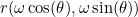 to find
  .
.
As each stage of this method uses the FFT, it is a lot quicker than calculating R directly by solving a lot of integrals.
The second important application is that the Fourier slice theorem gives us a way of inverting the Radon transform, so that we can find the function  if we know
  . In particular, substituting the formula for the inverse Fourier transform into the Fourier slice theorem and applying a change of variable formula we obtain
Or, putting everything together, we get the inversion formula
Bingo! Now knowing
we can find

every time.
Well, not quite. Like all inverse problems in tomography and other applications, the formula only works well if we know  very accurately and there is not too much noise in the results. Furthermore, there is quite a lot of work to do in calculating all of the terms in this integral, and errors can accumulate quite easily. In practice, this formula can be a bit unstable, and it is hard to implement accurately. However, it gives the basis for all other formulae used to find
  from . Indeed, one way to interpret the inversion formula is to note that
is the formula for the straight line at angle

and distance

from the origin, and the formula is combining the contribution of
along each of these lines. Developing this link leads to the
filtered back projection method, a rather more stable algorithm that is often used in practical scanning devices.
Return to the main article

![\[ e^{i\omega t}, \]](/MI/dec8f164491cf7a6b3935d52822a6baf/images/img-0005.png)
![\[ u(t) = \frac{1}{2\pi } \int _{-\infty }^{\infty } U(\omega ) e^{i \omega t} d\omega . \]](/MI/dec8f164491cf7a6b3935d52822a6baf/images/img-0007.png)
![\[ U(\omega ) = \int _{-\infty }^\infty u(t) e^{-i \omega t} dt. \]](/MI/43e041f7683cbf1aadbe83f56de1203c/images/img-0001.png)
![\[ U(\alpha , \beta ) = \int \int e^{-i(\alpha x+ \beta y)} u(x,y)dx dy. \]](/MI/bdbcba9ee1ac2d3aab28eb42d5d558d9/images/img-0009.png)
![\[ u(x,y) = \frac{1}{4\pi ^2} \int \int e^{i(\alpha x + \beta y)} U(\alpha , \beta ) d \alpha d\beta . \]](/MI/bdbcba9ee1ac2d3aab28eb42d5d558d9/images/img-0010.png)
![\[ r(\omega , \theta ) = \int R(\rho , \theta ) e^{-i \omega \rho }d\rho . \]](/MI/1ce20cf2ceac0cddd3dc303e13c926c7/images/img-0003.png)
![\[ r(\omega , \theta ) = \int \int u(\rho \cos (\theta ) - s \sin (\theta ), \rho \sin (\theta ) + s \cos (\theta ))e^{-i \omega \rho }ds d\rho . \]](/MI/1ce20cf2ceac0cddd3dc303e13c926c7/images/img-0007.png)
![\[ (x,y) = (\rho \cos (\theta ) - s \sin (\theta ), \rho \sin (\theta ) + s \cos (\theta )), \]](/MI/1ce20cf2ceac0cddd3dc303e13c926c7/images/img-0008.png)
![\[ \rho = x \cos (\theta ) + y \sin (\theta ) \; \; and \; \; dxdy = dsd\rho . \]](/MI/1ce20cf2ceac0cddd3dc303e13c926c7/images/img-0009.png)
![\[ r(\omega , \theta ) = \int \int u(x,y) e^{-i(\omega \cos (\theta )x + \omega \sin (\theta ) y)} dx dy. \]](/MI/1ce20cf2ceac0cddd3dc303e13c926c7/images/img-0010.png)
![\[ r(\omega , \theta ) = U(\omega \cos (\theta ), \omega \sin (\theta )). \]](/MI/1ce20cf2ceac0cddd3dc303e13c926c7/images/img-0012.png)
![\[ u(x,y) = \frac{1}{4\pi ^2}\int \int U(\alpha , \beta ) e^{i(x\alpha + y\beta )}d\alpha d\beta = \frac{1}{4\pi ^2}\int \int r(\omega , \theta )e^{i(x\omega \cos (\theta )+y\omega \sin (\theta ))}\omega d\omega d\theta . \]](/MI/e7984df1f472afe9cbd1437af30bd7a0/images/img-0003.png)
![\[ u(x,y) = \frac{1}{4\pi ^2}\int \int \int R(\rho , \theta ) e^{i\omega (x \cos (\theta )+y \sin (\theta ) - \rho )}\omega d\rho d\omega d\theta . \]](/MI/e7984df1f472afe9cbd1437af30bd7a0/images/img-0004.png)
![\[ x\cos (\theta ) + y \sin (\theta ) - \rho = 0 \]](/MI/4471dba7888d4704651bde2e39a14805/images/img-0003.png)