It's all in the detail
Cryptonite is not the first thing you expect to find in a beautiful rambling old house in the hills above Perth, Western Australia. But that, along with a bioraptor from the scifi movie Pitch Black, Rygel from television show Farscape and the foot of Olympic silver medallist Eamon Sullivan, is exactly what I discovered in the basement office of headus — a 3D scanning and software company run by Phil Dench and Jill Smith.
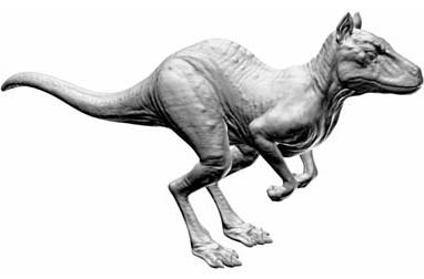
It's headus's very own killeroo! But what's under his skin?
The cryptonite, aliens and swimmer's feet are all highly detailed models that headus had been asked to scan using their 3D scanners, primarily for film and television companies. Often the first step in creating the life-like computer generated characters we are now so used to in the movies — such as King Kong, Iron Man, WALL-E and Gollum — is for an artist to produce a highly detailed physical scultpure of the creature, just like the ones that now decorate Dench's office. Once the studio is happy that the creature looks just right, a 3D scanner is used to produce a highly detailed three-dimensional digital model of the object that can then be manipulated by animators on a computer.
A 3D scanner shines a line of red laser light onto the object's surface, and a camera records the profile of the surface where the line of light falls. The position and direction of the laser and the camera lens are known, hence it is possible to calculate the position of each point on the surface highlighted by the laser (a unique triangle is formed by the point on the surface, the laser and camera, of which the length of one side and two angles — the orientation and distance between the laser and camera — are known). The three-dimensional coordinates of each point are stored digitally, building up an intricate mesh made from triangular faces that mimics the surface of the real object.
The resulting digital model is amazingly realistic — you almost forget that you are looking at a two-dimensional screen, and particularly that you are looking at a surface entirely made of flat triangles. The life-like quality comes from the massive amount of detail: a 3D scan can produce a model with as many as six million triangles making up the surface. The resulting model can be viewed on the computer screen either as a wire frame, or more realistically with each flat face shaded as it would be in real three-dimensional life.
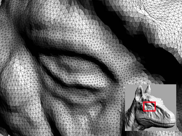
The image is actually made up of millions and millions of shaded triangles.
Trick of the light
The amount of light or shade falling on each triangle in the surface depends on the orientation of that triangle in relation to the light source. If a triangle directly faces the light source it will be lit brightly, but if it faces away from it, it will be in heavy shadow. This relationship between the orientation of the surface and the light source can be described simply with vector mathematics.
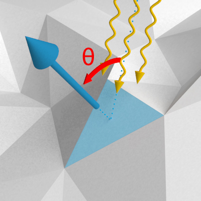
The shading of the triangle is determined by the angle θ between the orientation of the face (given by the perpendicular normal vector) and the light source (shown as wavey lines).
The orientation of each face on the surface of our model can be described by a normal vector — one which points perpendicularly out of the flat face. Similarly the direction of the light can be described by a vector, and the dot product (see box) of these two vectors gives a value indicating the angle between them (in fact the cosine of the angle). When a triangle is directly facing the light source the angle between the normal and the direction of light will be 0°, and the dot product between these two vectors gives a value of 1, indicating that the maximum amount of light would fall on that face and it should be shaded white. If a triangular face is almost side-on to the direction of light, so the angle between the normal and light direction is close to 90°, the dot product value is close to 0, indicating the triange should be shaded close to black, giving deep shadow. If a triangle is facing away from the light, so the angle is greater than 90°, then the dot product is negative; this is normally clipped to a value of 0 by the computer, giving the same black shading as a side-on triangle.
The dot product
To calculate the dot product of two vectors $v_1=(x_1, y_1, z_1)$ and $v_2=(x_2, y_2, z_2)$ you multiply their respective coordinates, and add them together: $$v_1\cdot v_2 = x_1x_2+y_1y_2+z_1z_2.$$ The dot product can also be written as the product of the length of the two vectors, and the angle $\theta$ between them: \begin{eqnarray*} v_1\cdot v_2 & = & \mbox{length of }v_1\\ & & \times \mbox{ length of }v_2\\ & & \times\cos\theta. \end{eqnarray*} For example, the dot product of two vectors, one lying on the $x$-axis and one on the $y$-axis, both of length one, is: \begin{eqnarray*} & (1,0,0)\cdot(0,1,0) \\ & = 1\times0 + 0\times1 + 0\times0 \\ & =0. \end{eqnarray*} And as these two vectors are perpendicular to each other (one on each axis), this agrees with the second definition of the dot product: \begin{eqnarray*} & (1,0,0)\cdot(0,1,0) \\ & =1\times1\times\cos(90^\circ)=0 \end{eqnarray*} as $\cos(90^\circ)=0$.
This shading happened fairly quickly on the computer Dench demonstrated to me as he spun the model in the virtual space of the screen, though the more triangles in a model, the more time it takes. This mathematical method for shading is such an integral part of how images are created on our computers that the computer hardware is now designed to carry out these calculations.
The life-like 3D model you can see on the screen is actually a highly detailed triangular mesh of light and shadows. But all this detail is precisely what makes the model almost impossible to work with — just spinning the model requires time for the computer to recalculate how to shade the millions of triangles (called rendering). And animators ideally want a model that more closely mirrors the aspects of the creature they want to animate; they want to be able to contract the muscles on an arm or raise an eyebrow, rather than deal with a fairly random mesh of triangles.
Remeshing — moulding to the surface
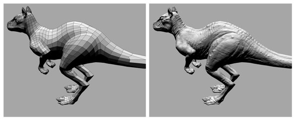
The next step in animating our CG creature is to remake the mesh so that it is easier for animators to work with. This remeshing involves reducing the number of faces in the model (say, from six-million to between five- and twenty-thousand faces) so that it is quicker for the computer to handle, and also altering the weave of the mesh so that it more closely follows the moveable parts of the creature.
Dench has created software that gives the animators the power to draw points on the surface of the model, which the software then joins up (by intersecting the plane defined by the normal vectors at these points with the surface of the model) creating a grid of lines that follow the flow and shape of the surface — following the lines of muscle, the form of a leg, the shape of an eye. This new mesh of quadrilaterals is much easier for animators to work with: not only does it contain far fewer faces reducing the computer power necessary, the new customised mesh now also shows much more clearly the shape and flow of the surface. Dench's software has been so successful, it has been used in major movies including King Kong, Happy Feet, Hell Boy 2 and Day After Tomorrow, and is now shipped with scanners sold throughout the world.
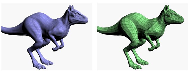
Two versions of the remeshed surface with different types of shading. These models are made up of far fewer shapes than the original tiangle mesh.
Flattening — it's about the detail
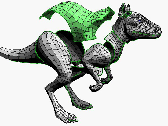
It's all very well having a mesh you can work with and animate, but the reduced wireframe, even with the lighting from the computer's imagined light source, still looks like a surface made up of quadrilaterals. The outline is chunky, particularly in silouhette and most of the textural details of the original model from the 3D scan are lost. This is where Dench's other clever piece of software comes in. Essentially, it serves as a dressmaker, making a near perfect costume so that our chunky, less detailed model can dress up as its highly detailed 3D scanned original.
We can dress our chunky wire mesh figure in the detail from the original detailed model.
The first stage is to skin the object. The animator chooses how to cut up the mesh in order to create pieces that can be flattened, that is, pieces that have the same topology as a sheet of paper.
The animator chooses how to cut up the model to create pieces that can be flattened.
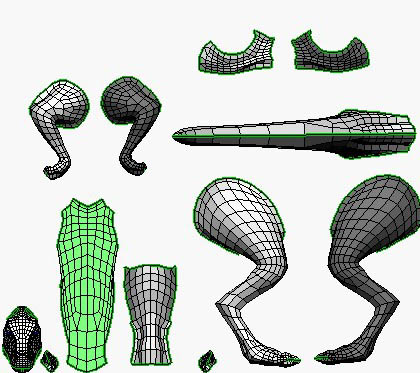
Next, just as a world map is a flattened version of the surface of the Earth, Dench's software flattens each piece of the sliced up model in order to create a pattern for its costume. Dench's flattening algorithm starts by initially directly projecting each three-dimensional sheet onto two dimensions: it literally just drops the z coordinates from the (x,y,z) vectors describing each point on the mesh. This produces a good result for the quadrilaterals that lie relatively flat, but those that are bent down and lie more side-on will be considerably shrunk or squeezed by this process.
 |
 |
On the left, you can see all the pieces of the model laid out ready to be flattened. On the right you can see the results of the first stage of the flattening process for the back piece, where it has been projected onto the plane. This has produced good results for the regions that lay relatively flat (shown in pale yellow), but the regions that wrapped around the sides have lost most of their width (shown in increasing shades of red) and the area that curled underneath has disappeared.
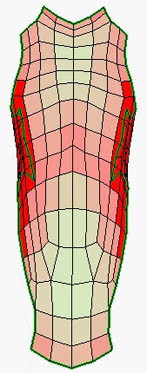
Finally a process of optimisation occurs, where, step-by-step, each quadrilateral applies a force to its vertices — pulling them in if it has been stretched or pushing out if it has been shrunk. The optimisation algorithm then adds all the forces at each vertex and moves it accordingly, again recording how well the shape of each quadrilateral represents the original. The difference, the error, is shown as colour, with stretched cells being shown in increasing shades of red, and shrunk cells shaded degrees of blue. Dench has designed the optimisation algorithm so that the forces applied at the vertices reduce with each iteration, until at some point the vertices would be moving by less than a pixel, and the process finishes as any changes would no longer make a difference to the final product. (You can watch a movie of the flattening process in action: choose from Windows media video format (WMV) — 1.6M or Shockwave flash format (SWF) &mdash 14M. The movie shows the flattening of two pieces of the killeroo. The accuracy of the process can be seen by the lack of distortion of the material (a sheet covered with numbers) of the pattern when it is folded to fit back onto the killeroo at the end of the movie.)
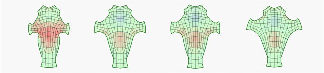
Several stages towards the end of the optimising process: quadilaterals are shaded according to how much they need to be stretched or shrunk.
In the end you get what looks very much like a dressmaker's pattern, all ready to be bent and stitched back together to create your creature. And now you have the pattern of the creature's costume, you just need to make it out of the right material.
Recreating the texture
This can be done in two ways. For applications that require quicker rendering time, such as the real-time rendering that occurs in computer games, you dress the creature in a normal map. This material is all the light and shadow seen on the original, detailed model painted onto the pieces of our creature's costume. Over each quadrilateral of the flattened pattern, the normals of all the finer triangles (from the original model) this quadrilateral contains are encoded. This means that each quadrilateral can be coloured with the light and shade of the original detailed model by calculating the dot products of these encoded normals with the direction of the light. It might look like the lumps and bumps of the original texture are back, but this is just a clever illusion. If you look at the profile you can still see the chunky outline of our simple model, but it appears to have all the surface texture of the original.
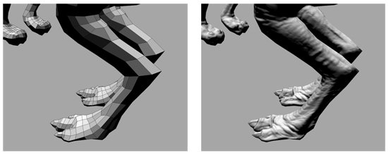
The chunky outline is still visible even after you've dressed the killeroo up with the normal map.
For applications that allow long times to render individual images of our creature, such as in the movies where each of the 24 frames shown per second can be individually rendered over hours and hours, there is another method. Instead of just painting the surface of our creature with an image of the texture the original had, we can instead reconstruct the detail itself. This is done through a displacement map. Encoded onto the dressmaker's pattern is exactly how far the points on the surface of the simpler mesh differ from the points on the original mesh. These take the form of positive and negative values for each pixel on the dressmakers pattern. When the costume is then applied to the simple mesh model, the detail of the original model is reconstructed point by point, as the simple mesh is pushed outward or pulled inward by the amount dictated by the displacement map.
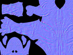 The information for the normal map is encoded into an ordinary image file, where the XYZ coordinates of the normals for each point in the pattern are represented by the red-green-blue values of each pixel in the image. |
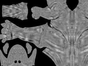 The information for the displacement map is encoded is also encoded into an ordinary image file, here the distance between the simple mesh model and the original detailed model at each point in the pattern is represented by the gray-scale value for each pixel. |
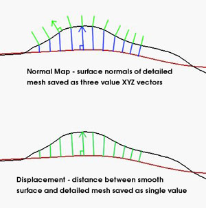
The information encoded into a normal map (top) and displacement map (bottom).
Whether you are producing a normal map (with painted details) or displacement map (with actual information on difference between surfaces), the complex information can be stored in a simple image file. Essentially the picture (usually a tiff file) is of the geometry of the flattened model, with the map encoded onto the pieces. Painted light and shade of the normal map is created by each pixel in the flattened pattern being encoded with the normal of the face of that point on the more detailed model; the vector representing the normal information is encoded using the RGB (Red, Green, Blue) colours, with the red value representing the x coordinate, green the y coordinate and blue the z coordinate. In contrast, the original detail for the displacement map is encoded at each pixel in the flattened pattern by using a grayscale representing the amount that the simpler surface differs from the real model at that point.
The rendering of life-like three-dimensional images on two-dimensional screens has amazed and fascinated us for centuries. Mathematics has always been pivotal, from the rules of perspective developed in the fifteenth century to the methods of encoding colours into the pixels of your digital holiday snaps. And with the software developed by Dench and his peers, we see how mathematics can bring the moving images of the virtual world to life.
About this article
Rachel Thomas, Co-Editor of Plus, interviewed Phil Dench of headus at their office in Rolystone, Western Australia.