The only way is up: constructing the Heron Tower
Looking out to Canary Wharf, to the arch at Wembley Stadium, and down onto the Gherkin, the 700 people working on the construction site of the Heron Tower in London have one of the best views in London as they eat their lunch in the site canteen on the 41st floor. Plus was lucky enough to take in this breathtaking view when Saverio Pasetto, Senior Construction Manager at Skanska for the Heron Tower, took us on a tour of the site. After catching our breath from walking down all the stairs from the 48th floor (phew!), we asked Pasetto and Jonathan Inman, Civil Engineer and Project Manager on the Heron Tower, how maths was involved in the construction of such an impressive addition to the London skyline.
You have to go down to go up
A building must have a solid foundation, and you'd assume that this needs to be constructed first before you start building your tower. Not so. The Heron Tower was built using top-down construction — where the basement and foundations were constructed at the same time as the tower. This diagram shows the steps taken to achieve this, with the red shaded areas showing the parts of the building that were built at the same time.
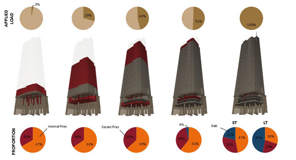
First an initial foundation was built by driving 12m long piles into the centre and perimeter of the site. Then the tower could be built at the same time as its permanent foundations.
Initially the foundation consisted of massive piles buried deep in the ground. Interjoined piles 12 metres deep formed a wall around the perimeter of the site, and more piles were installed into the ground in the centre of the site.
"Then we started working on two fronts, building up the steel work while excavating the basement and [pouring the concrete slabs in the foundation]" says Inman. Initially the team were able to build the steel skeleton of the tower by anchoring it to these piles. "But because not all the foundations were in we were constrained in how far we could go up, versus how far we went down so the thing didn't fall over. So we had a number of holding points, [or steps in the construction process,] to make sure we had reached far enough into the foundation to support the height of the tower [at all times]."
Calculating these holding points involved a number of factors. The weight of the building creates a vertical force pushing the tower down into the foundations: force = mass x g where g = 9.8 ms-2 is the acceleration due to gravity. So for the steel structure of a 48 story building weighing approximately 11,000,000 kilograms this vertical downward force is more than 107,800,000 newtons when finished.
The team also had to consider the lateral forces due to the wind that would push or pull the building sideways. The force from the wind depends on the surface area exposed to the wind (A), the wind speed (V), and the shape of the surface (the drag coefficient Cd, for example Cd=2.0 for a flat plate and Cd=1.2 for a cylinder).
The first holding point in the top-down construction process was that the tower couldn't go above 18 floors high until the slab in the second level in the basement was complete. And there were four more holding points until the foundations were completed, reaching three floors down and containing 12,000 tonnes of concrete and steel.
The top-down construction has been used for some time in the construction industry, but it is not common. It is sometimes used for large buildings because it speeds up the construction process, as long as there is enough time to be able to do the number of calculations needed to make it work. Building the structure of the tower at the same time as the foundations makes the construction process significantly faster with approximately six months being saved for the Heron Tower, which saves money too.
Coping with cranes
The cranes required to build a 46 story building are enormous. The three cranes used in the construction of the Heron Tower each weigh 220 tonnes and sit more than 200 metres above the London streets. Using free standing cranes would be far too expensive and take up too much space — they'd be enormous and require foundations of their own.
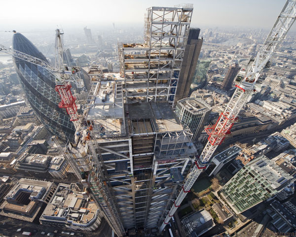
Three massive cranes were attached to the tower during its construction. The cranes on the south-west and north-west corners could be braced against each other. However the load of the third crane (on the far side of the building, hidden in this photo) had to be translated back into points of strength in the building.
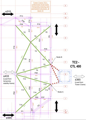
A section of the bracing diagram showing how the loads from the third crane (the blue square on the right of the diagram) were translated back into the building (via the bracing drawn in green)
Instead the cranes are attached to the tower, though the loads are so large that they still require their own foundations. But even though the tower does not support the weight of the cranes, it does need to take the lateral forces from the cranes created by winds and lifting loads. So during the construction process the tower has to cope with additional loads of around 2200 kilonewtons of vertical force and 190 kilonewtons of lateral force from the cranes.
"The cranes are heavy and [catch the wind], acting as a sail on a jib," says Inman. "They are attached to the building so they transmit those loads back into the building." Rather than just attach the crane at one point to the side of the building, the team at Skanska added bracing (a supporting framework) to the steel skeleton of the building to temporarily provide the additional strength needed to support the extra load of the cranes.
If the cranes were just hung onto the outside tower, the loads they lift in addition to the wind forces would pull the external structure of the tower out as well as down. Of the three cranes working on the Heron Tower, two sat opposite each other on the south-west and north-west corners of the building. These could be braced against each other, the outward force of one counteracting the outward for of the other, and vice versa.
The forces the third crane exerted on the tower could not be dealt with in this way. Instead, the engineers had to translate the forces back to points of strength inside the building. "We had to calculate how the building would carry this load, and created two levels of bracing deeper into the building," says Inman.
Leaning into the vertical
The construction process doesn't just have to take into account the temporary forces from the cranes, it also has to take into account the changing weight of the tower itself. In addition to the steel skeleton and concrete foundations and floors, the tower will also contain lift shafts and power plants to drive them, as well as plants for providing water, electricity and air around the building. And the whole thing is wrapped in a delicate skin of glass cladding.
"We can't wait until the structure is finished before adding the cladding and the lifts, they are all done at the same time" says Saverio Pasetto. "So as you are building, the whole structure is affected by what you are doing down below and this needs to be taken into account."
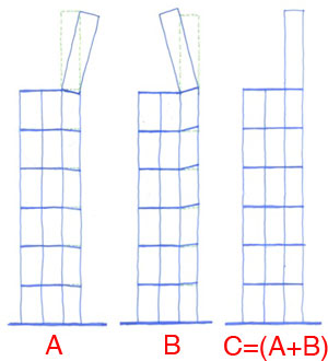
Diagram A shows what would happen if nothing was done to account for the shortening of the columns — the building would lean to one side. Therefore the building is built with a forward lean, diagram B, so that later the backward lean is cancelled out, resulting in a straight building, diagram C.
The tower is built in phases, but with different phases happening simultaneously as you move up and down the building. In January 2010 the steel structure was just being finished at the top of the tower, while the concrete floors were being laid in floors 38-41, the cladding and services being installed above floor 25 and the lift shafts and interiors being fitted below.
"There are different stages of construction all happening vertically at the same time," says Inman. And each addition affects the behaviour of the building. For example concrete floors stiffen the whole structure, but also add more weight. The building also has an unusual design — it is far higher on the southern side, going up to 48 floors compared with 41 floors on the northern side.
"The weight of the building is going down, but it is also going sideways," says Inman. "Because the building is eccentrically loaded there's more weight going down the southern side, and that causes a permanent sway." The extra weight of these floors combined with a sparser steel structure on that facade could have caused the building to tilt. But the engineers came up with an ingenious solution.
"We leant the building over," says Inman, though this wasn't as alarming as it sounds! Instead of being built vertically, the tower was initially built at a slight angle of 0.007 degrees, which was a tilt of 24mm at floor 38, "and gradually it's come back over during the construction process."
Under pressure
This initial tilt to the tower was accomplished by making the structural columns on the southern side slightly taller than those on the northern side, tilting the building to the north. And as more of the tower was constructed, the columns on the south side compressed more due to the greater weight on that side of the building, and the whole structure has gradually leaned back over to stand vertically.
"As the building goes up, the columns come under more and more load and they naturally compress," says Inman. "It is only a very small amount [in each floor], but when you get up to 40 stories and above the [total] compression becomes significant. That needs to be taken into account when you are designing and fabricating the steel work, and in the construction of the building." If you start with columns that are your desired final height initially, they will be compressed and your building will end up being, say, 100 millimetres too short.
To compensate for this compression structural engineers specify the columns over length: in the case of the Heron Tower some of the steel columns on the south side of each floor were 4 millimetres over lenghth, while the steel columns on the north side were just 1 millimetre over length.
The amount of shortening that occurs in each column is calculated by:
$$ \mbox{Shortening} = \frac{\mbox{Force on column}}{(EA/L)} $$ where $E$ is the {\em Youngs Modulus} of the material (a measure of the stiffness), $A$ the cross-sectional area and $L$ is the total length of the column.In fact it was even more complicated than that. "Compression doesn't happen uniformly across all floors," explains Inman. "The problem we have is that you have different shaped columns (with different cross sections). These have different ratios of cross-sectional area to load and they will compress at different rates." The rate at which columns will compress — the elastic capacity of the column — depends not only on the cross-section of the column, but also on the material the column is made of. For example, steel behaves very differently to concrete.
"So we have to allow for differential shortening of the columns," says Inman. "This is usually not that significant but in this building it was because of the nature of the design." The building is taller at some points, and there are different types of support structure across each floor. Each of these different support structures will compress at different rates, so some had to begin off relatively taller than others to account for this. "Initially the building looked like a tent [with the centre of the floor up to 45mm higher than the edges]. But gradually these difference levelled out over the course of construction."
But the compression isn't settled until everything is in place, so mid construction this can create some interesting effects. "We couldn't wait until the steel and concrete structures were complete before we added the lifts, and the scenic lifts on the south elevation are precise pieces of kit," says Pasetto. The lifts needed to be installed such that their doors opened exactly where the final floors of the building would be when it was finished. "So if you operated the lifts mid-construction they wouldn't stop at exactly the right level, but once you've finished the building and it had settled they would."
As this illustrates, a building like the Heron Tower is a dynamic beast during the construction process. Its behaviour is affected by the building's changing weight, the temporary loads of construction and the ongoing balance between forces from its surrounding environment. It is only when the structural engineers have done the calculations to tame this dynamic process that a new iconic building can be added to the London skyline.
About the article
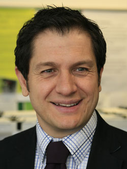
Saverio Pasetto
Saverio Pasetto is the Senior Construction Manager in Skanska. He joined Skanska in 2007 having worked as a Project and Site Manager for leading specialist façade contractors Focchi and Permasteelisa and has been involved in the last twelve years in some of the most prestigious projects in London. He previously worked in Italy as a façade designer and design manager and he is one of Skanska's most experienced façade specialists with over sixteen years in the cladding industry. Saverio is currently studying to obtain a Master of Science in Façade Engineering at the University of Bath.
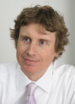
Jonathan Inman
Jonathan Inman is a civil engineer and Project Manager on the Heron Tower for Skanska. He is a Chartered Engineer, and has worked extensively across the South East of England with Skanska over the past 20 years on a wide variety of projects, including 30 St. Mary Axe and Heron Tower - two of most high-profile and complex steel framed buildings built in the City of London in the past ten years.
Jonathan is also a Supervising Civil Engineer for Skanska, providing a link with the Institution of Civil Engineers to develop the company's next generation of chartered engineers. He was awarded an MA in Management from the University of West of England in 2005.
Rachel Thomas, Co-editor of Plus, interviewed Saverio Pasetto and Jonathan Inman in London in September 2010.