
Snakes and adders
Most people probably know that computers work on 0s and 1s. And, being electronic devices, it's also pretty obvious that they work on some kind of electronic circuits. But how do these things fit together and how do computers actually manage to perform their tasks?
To give you an idea of how it all works, let's look at a particular example: how you can get a computer to add up natural numbers. The first thing you need to know is that every natural number can be represented as a string of 0s and 1s: that's called its binary representation, as opposed to the decimal representation we're used to. It's not too hard to get your head around binary numbers — see here if you don't already know.
Adding two binary numbers is easy. First, write one number underneath the other, so that their right-hand digits line up. Let's do this for the binary numbers 1111, which is 15 in decimal, and 1100, which is 12 in decimal:
| 1 | 1 | 1 | 1 | |
| + | 1 | 1 | 0 | 0 |
| | ||||
| Result goes here | ||||
Starting with the right-most column, do the following for each column in turn:
- Check the "carry" from the column on the right. This can be a 0 or a 1 (if you're looking at the right-most column, which hasn't got a neighbour on the right, then simply set that carry to 0). Look at the carry and the two entries of the column in question.
- If all three numbers are 0, then write a 0 underneath your column and carry 0 to the next column on the left.
- If exactly one of the three numbers is a 1, then write a 1 underneath your column and carry 0 the next column on the left.
- If exactly two of the three numbers are a 1, then write a 0 underneath your column and carry 1 to the next column on the left.
- If all three numbers are a 1, then write a 1 underneath your column and carry 1 to the next column on the left.
Here's what happens when we do this for our example (we've included a subscript of 1 in a column if there was a carry of 1 from the right.)
| 0 | 1 | 1 | 1 | 1 | |
| + | 01 | 11 | 1 | 0 | 0 |
| | |||||
| 1 | 1 | 0 | 1 | 1 | |
The result is the binary number 11011, which is 27 as required. The process might look a little unfamiliar at first, but it turns out that it's the exact analogue of adding decimal numbers.
Adders
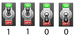
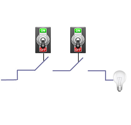
To get a computer to add two numbers, first notice that a binary number with n digits can be represented by a string of n on/off switches lined up in a row: the switch is on if the corresponding digit is a 1 and off if it's a 0:
Now imagine two rows of switches, one on top of the other, set so that they represent the two numbers you want to add. Each pair of switches in a column is connected to something called an adder (developed in the 1940s by the mathematician Claude Shannon) which we imagine as sitting right beneath the pair:
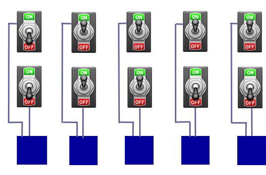
Each adder is also connected to its neighbouring adder, forming a snake of adders, and to a light bulb underneath. The position of the switches — whether they are on or off — will determine whether or not electrical currents reach the bulbs below and light them up.
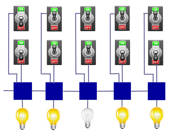
The idea is now this: remember that the two rows of switches represent the numbers to be added, written in binary. The adders now deal with electrical currents entering them in such a way that the result of the addition can be read off from the bulbs. If a bulb is on, write a 1, if it is off, write a 0. The resulting binary number should give you the sum you are after.
Let's think of each adder as working on three inputs. Two are determined by the two switches that sit above it and can be either on or off. The third corresponds to the input coming from the adder on the right and can also be on (if a current is arriving from the neighbouring adder) or off (if there isn't a current). This corresponds to the carry in the binary addition. To achieve the addition, each adder needs to do the following:
- If all three inputs are off, then don't let any current through to the bulb below and pass no current to the adder on the left.
- If exactly one of the three inputs is on, then let a current through to the bulb below and pass no current to the adder on the left.
- If exactly two of the inputs are on, then let no current through to the bulb below and pass a current to the adder on the left.
- If all three inputs are on, then let the current through to the bulb below and pass a current to the adder on the left.
Gates
How can we get the adders to behave in this way? Each adder is made up of a number of logic gates. You can think of them as electrical circuits with gates in them (transistors to be precise). Depending on whether the gates are closed or open, an electrical current that is being fed to the gate passes through, or it is blocked.
There are two very important logic gates. The first is called an OR gate, shown below. Let's imagine the gates as being operated by switches. When a switch is on, the gate is closed, and when it is off, the gate is open.
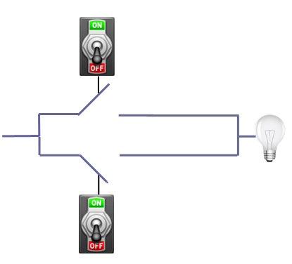
You can see that a current entering from the left passes through to the bulb when at least one of the two switches in on. If they are both off, the current won't pass through. In other words, the current passes through if one is on OR the other is off, hence the name.
The second is called an AND gate and it looks like this:
In this case, a current entering from the left only flows through to the bulb if the first AND the second switch are on, otherwise it won't.
Now suppose you connect two switches to two gates simultaneously, and add another gate, as follows:
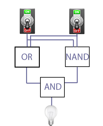
The NAND gate here is an AND gate followed by an inverter that reverses its output: if the two switches are on, the NAND gate blocks the current, otherwise it lets it through. Each gate, AND, OR and NAND, is supplied with a current with passes through if the two switches are in the correct configuration for that particular gate.
Let's see how the switches need to be set to light up the bulb.
| Switch 1 | Switch 2 | Output OR/input AND | Output NAND/input AND | Output AND/Bulb |
| On | On | On | Off | Off |
| On | Off | On | On | On |
| Off | On | On | On | On |
| Off | Off | Off | On | Off |
So the bulb comes on if exactly one of the two switches is on. This configuration is called an XOR gate, short for exclusive or.
Half adders
Now — hold your breath — let's wire our two switches to an additional AND gate as follows:
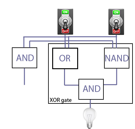
There are now two outputs. The one coming from the XOR gate is on exactly when one of the two switches is on, and the one from the AND gate is on only if both of the to switches is on. The whole configuration, the XOR gate and the AND gate, is called a half adder.
Let's return to our two binary numbers to be added, represented by two rows of switches. Let's wire two switches in a column up to a half adder, the output of the XOR gate to the light bulb underneath, and the output of the AND gate to the adder on the left.
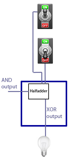
We now get exactly what we need to perform the addition when there's a carry of 0 from the right of our particular column. If both switches are off (so both numbers have a 0 in that column), the light bulb would stay off and there wouldn't be a current to the left. If both switches are on (so both binary numbers to be added have a 1 in that column), the light bulb stays off and there is a current to the left. If exactly one switch is on (so exactly one of the two numbers has a 1 in that column), then the light bulb comes on and there isn't a carry to the left.
Full adders
But how do we deal with a carry from the right, that is, with current coming from the neighbouring adder on the right? To do this, we include another half adder, wired up to the existing half adder, an additional OR gate, and to the adder on the right as follows (we have labelled the outputs from the half adders to indicate if they come from the XOR or the AND gate within the adder):
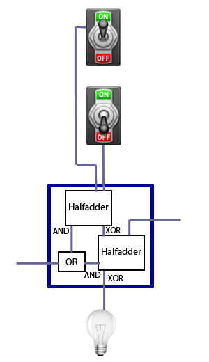
This is starting to look rather messy, but by doggedly following what happens to currents fed to the gates, you can see that the full adder does exactly the right thing. For example, suppose that one switch is on and one is off, and there's a current from the adder on the right of the one we are looking at. As we saw above, in order to implement the addition, the bulb should stay off and a current should be passed to the left. And this is what happens. The half adder wired to the switches passes a current to the second half adder, via its XOR gate. The second half adder also receives a current from the right, and therefore passes no current to the bulb via its XOR gate. The OR gate receives no current from the first half adder (via its AND gate), but it does receive one from the second (via its AND gate), which means it passes a current on to the adder on the left.
And this is it! This is how you can get a computer to add up natural numbers. The set-up may strike you as quite complicated for such a basic task. But the good news is that even more complicated tasks can be implemented using only AND and OR gates, and a NOT inverter (in our example this was coupled with the AND gate to produce the NAND gate). In fact, any computer algorithm can in theory be implemented using only a combination of NAND gates, or a combination of NOR gates (an OR gate followed by a NOT inverter).
About this article
Marianne Freiberger is Editor of Plus.
Comments
Anonymous
Interesting article, thanks. One typo:
"But how do these things fit together and how to* computers actually manage to perform their tasks?"
:)