Designing loudspeakers
In his first article "Natural frequencies and music", David Henwood introduced the idea that most structures vibrate at natural frequencies when excited (for example, by hitting them) and become deformed into corresponding shapes or modes as a result.
This property of vibrating naturally at certain frequencies is the means of creating music, but it is the major cause of problems when the music is being reproduced, say through a loudspeaker. The phenomenon which was the source of the original sound becomes distortion. The difficulty arises because the structural parts of a loudspeaker will each have their own natural frequencies which may influence the sound - when they shouldn't.
The loudspeaker cone is forced to vibrate by an electric current passing through a coil at its base set in a magnetic field. When the cone vibrates, the vibration is transferred to the air and thus to our ear-drums. In this article we consider briefly two aspects of the loudspeaker. Firstly, the vibration of the cone itself and secondly, the air in the box or cabinet which contains the cone. This air is set in motion by the rear surface of the cone.
Figure 1: Modes of a speaker cone.
Finite elements
Mathematics is useful in trying to understand these processes by being able to model them. It can represent in detail the geometry of particular shapes, and knowing the correct parameters for materials it can predict the natural frequencies and mode shapes of the vibrating structure. Thus without having to build a physical proto-type and observe (perhaps with a laser) how it behaves, a mathematical model can be made through a computer program and the results shown on the computer screen. In this way the basic behaviour and the effects of small modifications can be observed, giving the design engineer a powerful aid.
A common mathematical method used to do this is called finite elements. As its name suggests, the basic idea is to represent a complicated structure by a number of small regular shapes over each of which the assumption of a simple behaviour is valid.
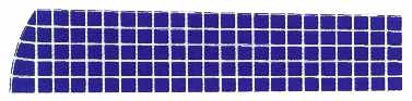
Figure 2: A finite element mesh dividing part of a horn into squares.
Other applications
The method of finite elements was developed in the late 1950s in the aircraft industry because of the need to analyse how various parts of the wings and fuselage of a plane distort under pressure, and how they respond to vibrations.
It was discovered that many other different physical problems may be analysed by the same approach; heat flow, magnetic and electrical fields, acoustics... The variables defining the simple shapes are used together with the physical laws relating an applied force with the resulting displacement, and are brought together into a large set of equations. The form is the same as for the simple mass on a spring (see "Natural frequencies and music") but now u is a vector whose terms are the displacements at a (large) number of points defining the structure, and M and K are matrices describing the mass and stiffness of various parts of the structure.

Many design engineers, civil, mechanical, and including those in the Hi-Fi industry, now have available in their offices interactive computer software which makes it easy (relatively) to use this mathematical tool.
The Nautilus loudspeaker
Ideally a loudspeaker cone should respond equally to excitations throughout the frequency range so as not to favour one more than any other. However, the cone does have a set of natural frequencies and when excited at these it will resonate - respond more than at the others.
This is a problem and there is no easy solution; by making the material stiffer the frequency at which they occur can be raised and by making the cone of a material that absorbs energy (like kevlar) their effect can be spread and be not so noticeable. All loudspeaker companies have to contend with this problem but Lawrence Dickie, engineer at B&W and designer of the Nautilus loudspeaker, went for a rather radical approach.
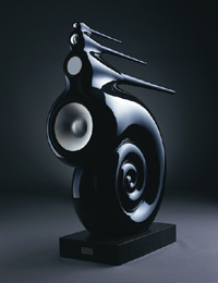
Figure 3: The Nautilus loudspeaker
A standard procedure is to divide the frequency range into two or three parts and electronically organise each part of the frequency range to be allocated to a separate cone. In doing this each cone can be designed to cater for a limited range, and its shape and material can be chosen so that its natural frequencies do not spoil the sound. Lawrence Dickie chose four as you can see from the
photo. He used the material kevlar for the base unit and less usually aluminium for the other three [Correction]. His ideas on shapes and materials were tested out before the prototype was made using a finite element model.
Box resonances
The other problem with loudspeaker design is with the cavity resonances of the box. One shape which is known to inhibit air resonances is that of a horn which tapers exponentially, so that its profile has the form:
where a and b are suitable constants.
This is technically better than the usual rectangular box whose resonances are more pronounced, but the horn shape is more difficult to manufacture. You can see them on the Nautilus for the high and mid-range domes. The large cone for the lower, base, frequencies gave a problem as the necessary length was too great. The solution was to curl it up into the shape you can see. This in itself gave a mathematical problem - how can you design a curled shape whose cross sectional area decreases exponentially and, more difficult still, how can the thickness of the wall be included? Finite elements will not help here, it needs geometry and a numerical approach.
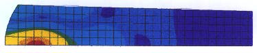
Figure 4: The computed pressure contours for the finite element mesh of figure 2.
Even the exponential shape is not perfect as you can see from the computed pressure contours in the picture above based on the finite element mesh for part of half of a rear horn (see above). On listening to the loudspeaker some distortion was noticed at about 10,000Hz so this was modelled and the computed picture shows a build up of pressure near the dome. The mathematical model shows what was going wrong, the engineer has to decide what to do about it!
Mathematics can be useful!
B&W employ a mathematics/physics graduate, who obtained a PhD through work on this kind of modelling together with optimisation. They also use a mathematician on regular occasions to help with their development. So you see that mathematics can be useful!
About the author
David Henwood is a Senior Lecturer of mathematics at the University of Zimbabwe.
Acknowledgements
PASS Maths would also like to thank B&W Loudspeakers Ltd of Worthing, UK for their help in preparing this article.