
Got your popcorn? Picked a good seat? Are you sitting comfortably? Then let the credits roll...
Mathematics proudly presents...
We have all marvelled at the incredibly life-like computer generated images in the movies. What most of us don't realise is that the dinosaurs of Jurassic Park and the wonders of Lord of the Rings — particularly the star turn of Gollum — would not have been possible without mathematics.
But how are these amazing images made? Computer graphics and computer vision are huge subjects. In this article we will take a simplified look at some of the mathematics it takes to get to a final product. First we'll create the world seen in the movie, and then we will bring it to life.
Setting the scene
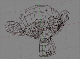
First objects are modelled as wire skeletons made up from simple polygons such as triangles.
The first step in creating a computer generated movie is to create the characters in the story and the world they live in. Each of these objects is modelled as a surface made up of connected polygons (usually triangles). The vertices of each triangle are stored in the computer memory. It's important to know which side of the triangle is on the outside of the object or character. This information is encoded in the order the vertices are stored in, according to a right-handed screw rule: curl the fingers of your right hand around the triangle in the order given by the vertices. There's only one way to do this and your thumb will end up on one side of the triangle — that side is the outside. If you try this with an example, you will find that the outward direction (called the outward normal) of the triangle (A,B,C) is in the opposite direction to that of (A,C,B).
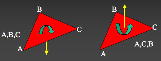
The outward normal of (A,B,C) is in the opposite direction to (A,C,B) as determined
by the right-handed screw rule.
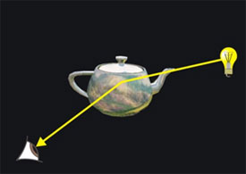
Trace a ray from your viewpoint to a facet. Does it reflect off and intersect a light source?
Now that the surface of our object is a wire mesh of triangles, we are ready to colour each of its components. Here it's important to realistically capture the lighting of the scene we're modelling, and this is done using a process called ray tracing. Starting from our viewpoint, we trace rays backwards towards the object and let them reflect off it. If the ray from our eye reflects off the facet (one of our wire mesh triangles) and intersects a light source, we shade that facet in a bright colour so that it appears lit up by the light source. If the reflected ray does not meet the light source, we shade the facet in a darker colour.
To trace a ray back to a particular facet, we need to describe the surface mathematically, and solve geometric equations involving the ray and the plane described by that facet. This is done using vectors. We impose a three-dimensional co-ordinate system on our scene with the origin — the point $(0,0,0)$ — placed at our view point. A vector $v=(a,b,c)$ now denotes the arrow starting from the origin and ending at the point with co-ordinates $a,$ $b$ and $c$. We can multiply $v$ by a number, the number 2 say, according to the rule $$2v = 2(a,b,c) = (2a,2b,2c),$$ so $2v$ is the arrow pointing in the same direction as $v$ but twice as long.
Now look at the expression $\lambda v,$ where $\lambda$ is a variable, in other words any real number. This no longer indicates an arrow of a certain length, since the length has become variable, but only the direction of the arrow. In other words, the expression describes the line that contains the vector $v.$ It describes a straight line — a ray — emanating from the origin — our view point — in the direction given by the vector $v.$
The plane defined by our triangular facet can be represented by three pieces of information: the location of one of the three vertices, call it vertex $a_1$, together with the vectors representing the line from $a_1$ to the vertex $a_2$ and the line from $a_1$ to the vertex $a_3$.
The box below gives the equations of a ray starting from our eye and the plane given by a facet. To find out if and where the ray intersects the facet and to calculate the equation of the reflected ray, we need to solve equations involving these two expressions.
| Equation of a ray, where $\lambda$ is a real number and $v$ is a vector: $$ r = \lambda v $$ |
| Equation of the plane defined by a facet with vertices $a_1, a_2$ and $a_3$: $$ r = a_1 + \mu_1 (a_2 - a_1) + \mu_2 (a_3 - a_1) $$ |
(You can read all the mathematical details of ray tracing in Turner Whitted's groundbreaking paper "An improved illumination model for shaded display", in Communications of the ACM, Volume 23, Issue 6.)
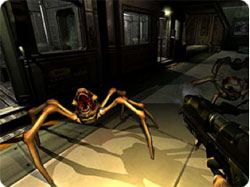
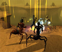
Ray tracing can produce realistic scenes but it is very slow. This is acceptable for producing computer generated movies, but becomes a problem when you need lighting to change in real-time, such as in computer games. Complex phenomena such as shadows, caustics and multiple reflections are hard to model dynamically and more sophisticated mathematical methods, for example precomputed radiance transfer and radiosity are used here.
 |
 |
|
Computer games such as Doom 3 and Neverwinter nights require dynamic lighting |
|
All it takes is a little imagination
Once our scene is set, and lit, we are still waiting for the director to shout "Action!" and our characters to start moving. Now we will examine the maths that can bring our images to life.
One of the most basic movements an object can perform is a rotation around a given axis and through a given angle. Co-ordinate geometry gives us the tools to calculate the position of each point on the object after it has been rotated, but it's important that these tools are efficient and fast.
To find these tools, let's take a step back into the maths classroom. We know that there are two square roots of $25$: $+5$ and $-5$ as $ (+5)^2=(-5)^2=25. $ But what is the square root of $-25$? To find the square root of negative numbers, mathematicians had to create a new number, called $i$, where $i^2=-1$. Then as $ (\pm 5i)^2 = 25i^2 = -25, $ we find that $\sqrt{-25}=\pm 5i$.
The introduction of $i$ meant that equations like $x^2=-1$ could now be solved. And numbers of the form $z=x+iy$, called {\em complex numbers}, became an important tool in mathematics. But many people were not happy with this strange new imaginary number $i$. (You can read a brief introduction to complex numbers in last issue's Unveiling the Mandelbrot set and the previous article Curious Quaternions.)
Finally in 1806 the amateur mathematician Jean-Robert Argand gave a geometric interpretation of complex numbers and $i$. Argand associated complex numbers with points in the plane with the real number $1$ sitting on one axis, and the imaginary number $i$ sitting on the other. For example the number $1+i$ corresponds to the point (1,1). Generally, a complex number $a + ib$ corresponds to the point (a,b).
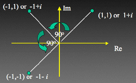
Multiplication by complex numbers has a geometric description — rotation.
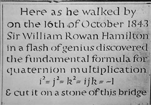
The commemorative plaque now on Broome Bridge, under which Hamilton was walking when he discovered quaternions.
Moving to 3D
The mathematician Sir William Rowan Hamilton is perhaps Trinity College Dublin's most famous son. He devoted the last two decades of his life to searching for a way to represent 3-dimensional rotations in a similar manner as complex numbers can represent rotations in two dimensions.
Towards the end of his life Hamilton discovered the answer, in the form of something he called quaternions: numbers of the form
$$ q =a_0+a_1i+a_2j+a_3k $$ where $i^2=j^2=k^2=ijk=-1$ and $a_0, a_1, a_2$ and $a_3$ are real numbers.
Just as we did for complex numbers, we can describe quaternions geometrically and use them to represent rotations. But this time rather than rotations in two dimensions, these are rotations in three-dimensional space.
To do this the $i, j$ and $k$ represent the {\it elemental planes} in three-dimensional space: that is $i$ represents ths $yz$ plane, $j$ represents the $xz$ plane and $k$ represents the $xy$ plane, with outward normals in the $x, -y$ and $z$ directions respectively.
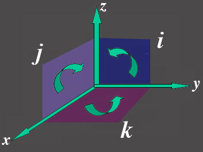
The i, j and k can be geometrically interpreted as the elemental
planes of three-dimensional space.
Suppose we wish to rotate a point $a=(a_1, a_2, a_3)$, through an angle $\beta$ about an axis through the origin given by a vector $b=(b_1, b_2, b_3)$. We construct two quaternions $q_1$ and $q_2$ using this axis vector $b$ and the angle of rotation $\beta$: $$ q_1 = \cos (\beta/2) + \sin (\beta/2) (b_1 i + b_2 j + b_3 k) $$ and $$ q_2 = \cos (\beta/2) - \sin (\beta/2) (b_1 i + b_2 j + b_3 k) . $$ Then we can multiply $a$ (expressed as a combination of the unit vectors in the $x, y$ and $z$ directions) by these two quaternions (obeying special rules for multiplying the planes $i, j$ and $k$ and the unit vectors) to give: $$ a' = q_1 a q_2 . $$ It turns out that the point $a'$ given by this multiplication is exactly the point you get to when you rotate $a$ around the given axis through angle $\beta$! So just as complex numbers can be used to describe rotations in a plane, quaternions can be used to describe rotations in three-dimensional space.
Hamilton's flash of brilliance, as he walked under that bridge in Dublin, turns out to be the most efficient way to rotate objects in three dimensions. But not everyone was happy with his new method of multiplication. Lord Kelvin, the physicist, said of quaternions: "... though beautifully ingenious, have been an unmixed evil to those who have touched them in any way!"
Particularly worrying to some was the fact that when you multiply two quaternions the answer depends on the order in which you multiply them, a property called {\em non-commutativity}. For example, from Hamilton's multiplication rule, it can be shown that $ij=k$ and $ji=-k$. However it can be shown that when one treats the $i, j$ and $k$ as elemental planes, the properties that were so worrying to Kelvin and his contemporaries follow directly from the mathematics.
Bringing the images to life
Hamilton's invention is now used in many graphics applications to move objects or create motion. Two of the most important tools in computer graphics are deformations and interpolations. Interpolation and the technique of keyframing involve specifying an object's initial and finishing shape and position and getting the computer to work out the stages in between, as shown in the image below.
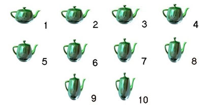
The shape of the teapot gradually changes over a series of frames.
You can see an animation of a rudimentary snake (created by Richard Wareham), where the whole snake is created by the computer using interpolation from the movement of a few specified points — download the 2.3Mb file (your movie player may require some additional software available from DivX).
Deformations are a way of creating complex objects from simpler ones. A cloth falling over a deformed sphere, as in the image below, can be derived by mathematically manipulating the same scene involving an ordinary sphere. Both deformations and interpolations require fast and stable mathematical techniques and quaternion-related methods provide just those.
 A cloth falling over a round sphere can be |
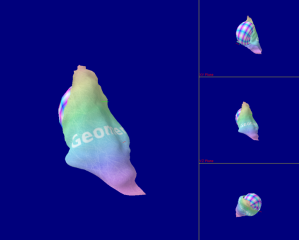 ... and then manipulated to give a cloth |
Making Gollum believable
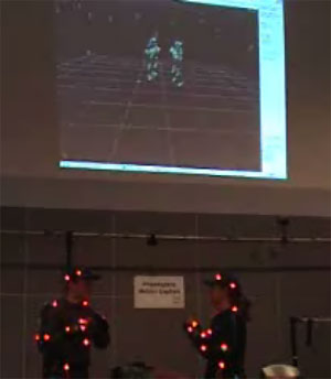
The techniques described above are essential tools for classical animation, and we are quite happy to believe their results for cartoon characters. But when used to animate humans we can immediately spot it as false. To create realistic motion, generally motion capture is required.
Many characters, such as Gollum from the film version of Lord of the Rings, are built using motion capture. This is done by attaching reflectors to real people at pivotal points of their body — their head, shoulders, elbows, knees, etc. The individuals are filmed by multiple cameras and the changing position of the reflectors is stored on a computer. A skeleton is then fitted to the 3-dimensional data. Finally, all the techniques described above are used to put flesh on the bones and create a living, breathing, moving character.
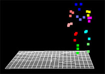 Data is captured from the movements of reflectors attached to different parts of the body... |
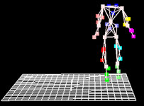 ... and a skeleton is mathematically fitted to the data. |
If you've ever stayed to watch the entire credits roll you'll be aware that a huge variety of creative talent goes into making a successful movie: writers, directors, actors, costume designers, prop builders... the list goes on. But one name is often missed off that credit list — mathematics. Many of today's movies wouldn't be possible without the geometry of ray tracing or quaternions spinning objects in space. So the next time you settle into your cinema seat to enjoy a CG spectacle, raise your popcorn to mathematics, the hidden star of the show.
Try it yourself!
If you want to find more about how quaternions achieve the impressive feats mentioned in this article, try these three problems on our sister website NRICH:About the author
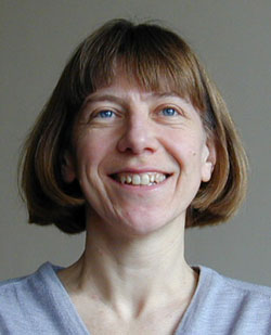
Joan Lasenby read Mathematics at Trinity College Cambridge. This was followed by a PhD in the Physics department in the Radio Astronomy Group. After a brief spell in industry working for Marconi, she returned to academia and is now a University Lecturer in the Signal Processsing Group of the Cambridge University Engineering Department and a Fellow and Director of Studies at Trinity College. Her research interests lie in the fields of computer vision, computer graphics, image processing, motion capture and geometric algebra.