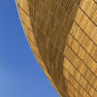
The Velodrome, with its striking curved shape, was the first venue to be completed in the London Olympic Park. Plus talked to structural engineers Andrew Weir and Pete Winslow from Expedition Engineering, who were part of the design team for the Velodrome, about how mathematics helped create its iconic shape.
Round and round
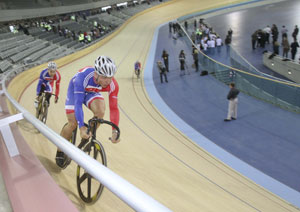
Sir Chris Hoy leads the GB Cycling Team during the official opening of the Velodrome (Photograph by David Poultney)
During the Games all eyes in the Velodrome will be on the curled ribbon of wooden track at its centre. The track was designed by world famous track designer Ron Webb. While the exact geometry of the track is top secret, Weir and Winslow can tell us that like any competition track it has to conform to the International Cycling Union's rules. Therefore it has to be 7 metres wide. It can be be made out of materials other than timber (eg it could be made out of concrete) as long as it is planar (ie its cross-section is flat) and a line circling around the track has to be 250 metres long. "So it doesn't have to be banked," says Weir. "The whole thing could be flat, circular or almost anything." (You can read more about why velodrome tracks usually do have steeply sloped turns in Leaning into 2012.)
The track in the London Velodrome doesn't have the usual reflection symmetry you find in buildings. "If you folded the track in half lengthwise, the two halves wouldn't match," says Weir. The track does have rotational symmetry, it looks the same if you spin it by a half-turn. But the slope of the track going into and out of the turns is not the same. "This is simply because you always cycle the same way around the track, and you go shallower into the turn and steeper out of it."
Although the difference in the banking going into and out of the turns is only fractional this does place constraints on the building. In particular the differences in height mean that the track is not symmetrical when you look at each end in isolation. "The difference in height means that the way we've arranged the seating [around the turns] isn't symmetrical. But obviously to make a building effecient you want to get back to symmetries as much as possible. So just a couple of rows back from the front seat we've got back to symmetry."
Designing from the inside out
Traditionally buildings were designed by thinking of their final form and making sure the building then suited its purposes. But the Velodrome was designed in the opposite way. Instead of starting from a final form Weir, Winslow and their colleagues at Hopkins Architects focussed on the constraints placed on the building by its use as a velodrome.
"One of the key things in any sporting venue is basically how good the sight-lines are," says Weir. "There are ways of measuring sight-lines, effectively what you see in a line from your eye over the head of the person below. Very steep terraces are very good, in that the person below is a lot further down. But there are access issues and you can only have a certain staircase inclination. "
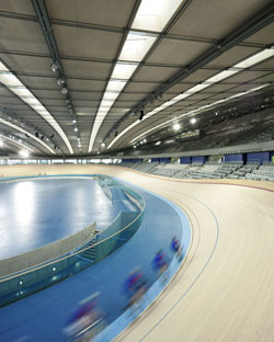
Ensuring all spectators had good sight-lines onto the track was one of the constraints on the design (Photograph by Richard Davies)
To resolve all these constraints the design team used a computer aided design method called parametric modelling. "Traditionally computer aided drawing works the same way you would draw the designs on paper," says Winslow. "Rather than a pencil and a ruler you have a mouse and draw a particular object with specific dimensions. And then afterwards you can check: Do we have sight-lines? Do we have the right space for the structure and so on."
"But in parametric modelling you don't start off by drawing lines; you start off by saying, what are the rules that we need to apply?" The rules Winslow and his colleagues had to apply included things like that the seating pitch can not be greater than a certain angle for safety, and that every seat needs to have a sight-line onto the track. "And you can imagine there is a whole bunch of rules you can build up from that. And then, there is only a small number of ways you can resolve all those rules at the same time, and that gives you your geometry."
So, rather than containing a fixed shape of the final building, the computer model contains the relationships between all the variables that constrain the final geometry. This allows the designers to play with the building and explore many different options. For example small changes, such as changing the distance between seats from 800 to 850 millimetres, ripple through the model. "If you made the seats slightly further back you could see the effects on everything else in the building," says Weir. "What's good is you can cover a lot of ground very quickly with parametric design, to know if you're heading in the right direction."It's better to be curved
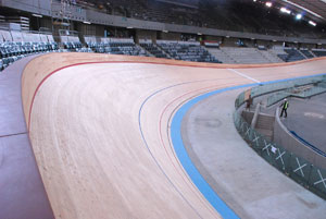
Two rows of seating were included around the turns to create a "wall of sound"
And although one of the most striking features of the velodrome is it's doubly curved roof, again this shape is a by-product of this inside-out design process. Although many factors contributed to the roof's final form, it was essentially down to making the best possible venue for spectators and cyclists.
"What we're looking for is a fantastic experience for those people inside the stadium. But equally we don't want to build a stadium that is twice as big as we need to," says Weir. "We've always had this idea that we'd shrinkwrap the building to the form that's inside. We have to put in a track, we have to put 6,000 seats around it, each one of those seats being a nice place to sit. But we didn't want to build anything more than that."
Normally velodromes have very few, if any, seats at the ends of the track. This is because at this point the track is very steeply banked at 42 degrees. "It's not a particularly good place to sit. The track is so steep you can't really look down and see what's going on in front of you," says Weir. "And as the maximum rake of a seating tier is about 34 degrees that is going to get worse the more seats you put at the ends."
But this concern for spectators also had to be balanced with the interests of the competing cyclists. "The feedback we had from the cyclists is when they are going around a velodrome you get a lot of excitement on the straights but when you get to the ends it's almost like a deathly silence." So the designers compromised; they included two rows of seats at each end, providing the "wall of sound" the cyclists were looking for.
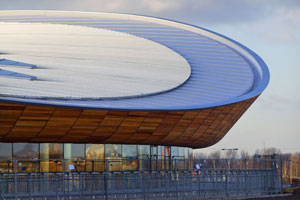
The roof curves in the opposite way to the rise and fall of the track (Photograph by David Poultney © ODA 2008)
"So there is some continuity of spectators but the bulk of the 6,000 seats are at each side. And as you can imagine that builds up the height of the building at the sides of the track, but at the ends there is very little. So you get two high points [at the sides] and two low points [at the ends]."
Surprisingly, the rise curves in an opposite way to the rise and fall of the banked track it covers. "Shrinkwrapping [the track and surrounding seats] gives you a building that's pulled down at the ends but pulled up on the sides." And an added benefit is that this doubly curved shape is the most efficient structural form for a roof.
The roof of the Velodrome was constructed using a cable net design. The cables that hang down in one direction pull against those cables laying across them in the other direction and the opposite curvatures of these two sets of cables play off against each other. "One set really wants to go up and the other really wants to go down and they hold each other in place," says Weir.
This is an incredibly efficient design in terms of materials needed to construct the roof. If you imagine a cable hanging between its two suspended ends it naturally falls into a shape called a catenary curve, where each bit of steel in the cable is working at its highest efficiency. "In structural engineering we call this process of finding the [system's] minimal energy form finding, " says Winslow.
In comparison, if you have a roof that isn't curved you need a different way to carry the load. In a flat roof the load is carried by the stiffness of the beams resisting any bending. "On a simple level if you look at a structure that's flat, say the ceiling in every office or school, then the material in the top of the beams is in compression and the material in the bottom is in tension. The material in the middle does very little," says Winslow. In contrast, every bit of steel in the cable net roof of the Velodrome is providing essential support.
Modelling one piece at a time
Any roof has to withstand anything that nature might throw at it— the roof might be lashed by heavy gales or heavy snow might pile on one side. As well as checking that the roof of the Velodrome would hold up in all these different situations, called load cases, the engineers had the added complication of dealing with movement.
"Imagine a tennis racket. As a ball hits the racket you can imagine each square in the net deforms a little bit. And our roof does exactly that," says Weir. "And you can imagine every little square between the cables moves a different way," says Winslow.
Traditionally movement in a cable net roof isn't so much of a problem as they are usually covered by flexible material. "But because we are trying to meet very high levels of sustainability we have a very heavily insulated roof." The insulation sits above the wooden ceiling panels that hang underneath the cable net structure. "In addition the planners [of the Olympic park] wanted us to use a particular type of roof called an aluminium standing seam roof," says Weir. This roof is basically lots of long panels of aluminium laid side by side along the roof and joined by rolled seams. "And it is a system that really doesn't like movement"
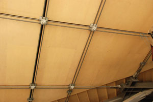
The wooden ceiling panels are attached to the cable net with specially designed articluated joints
"So we've got a cable net that does move around a little bit, then we've got lots of insulation, then we've got this roof system on top that doesn't like movement but looks very nice."
Winslow's job was to make sure all the movements resulting from all the different possible loading cases would be isolated from the delicate ceiling panels and unmoving aluminium roof. To see how it would react he mathematically modelled the whole structure in terms of its stiffness and strength properties. "In structural engineering you use a lot of finite element models which break down the structure into lots of small components — lots of small steel elements and lots of small cable elements — and we know very precisely what the stiffness of that small element will be." The equations describing the movement of these small parts can be solved exactly but they become too complex to solve when you consider the whole structure as a sum of these small pieces. Instead finite element analysis creates a mathematical model of how all these small pieces fit together and simulates how the roof as a whole will move.
And Winslow didn't just have to consider all the different load cases the environment might place on the roof; he also had to consider the many different loading situations that would occur during the construction process. Each time one of the thousand timber ceiling panels was hung in the hole between crossing cables those cables would move slightly. Similarly installing every light, pulled up by a pulley, caused a local deformation of the roof.
Once Winslow understood how the roof was going to move, he could solve the problem of how the solid timber panels and delicate standing seam roof would cope with that movement. The timber panels are attached to the metal clamps that hold the cables together at each crossing point. The design team devised an ingenious articulated joint, sitting at each clamp, that allows the cable net to move without crushing or cracking the timber panels. And to isolate the aluminium roof from the movement of the cable net Winslow had to carefully align these articulated joints, orientating these connections to make sure movement only happened in the directions that the alumnium roof could cope with.
In modelling the roof, Winslow used vector calculations to analyse the movements of the structure: "Dot products and cross products to work out how much movement occurs in certain directions. So it turns out that all the fundamental maths I learned long ago does have some applications!"
And although the mathematics may have been straightforward, the volume of calculations involved in modelling the roof was enormous."There's a thousand [ceiling] panes and there's hundreds of load cases, and the interelationship between one panel and all it's neighbours," says Weir. "We're not aware of any other roof that has had that level of analysis."
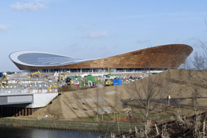
(Image by Richard Davies)
Finding the right form
One of the most striking features of the final design is the way its sweeping shape gives a sense of the curved track within. "When you look at the velodrome there is a really nice relationship between the track and its banking and the roof's curvature. It wasn't planned like that but it's a happy by-product of the design," says Weir.
The final design of the building is the solution to a large set of competing problems – optimising the structure, accommodating the geometry of the track, optimising the seating and temperature for both spectators and athletes.
And by successfully dealing with all these constraints, the final form of the velodrome gives you a similar sense of satisfaction and correctness that comes from finding the exact solution to a mathematical equation. "All of us look at this form and think it's optimal," says Weir. "The architects like it for the architecture. The service engineers thinks the building is fantastic for how it works for them. And structurally we think it is great."
"It's good design to be honest and it comes from getting [the constraints] right at the beginning. Maybe there's a bit of luck in it. Or maybe this structure was just really crying out for this form."
About this article
Andrew Weir
Andrew Weir has a wide range of experience in structural and civil design varying from large multi-disciplinary transport schemes to high quality architectural engineering. He also has an MSc in Earthquake Engineering & Structural Dynamics. Since joining Expedition Engineering, Andrew has worked with the Richard Rogers Partnership on designs for the Capodichino Metro Station in Naples and with Renzo Piano Building Workshop on a 45 storey tower in Turin. As well as working with Hopkins Architects on the 2012 London Olympic VeloPark he is also currently working with RPBW on the Stavros Niarchos Foundation Cultural Centre in Athens.
Pete Winslow
Pete Winslow joined Expedition Engineering in mid-2009 after studying for a PhD on multi-objective optimization of free-form structures. Prior to joining Expedition Pete has worked as a specialist sub-consultant, applying his advanced knowledge of complex geometry, optimization and pedestrian dynamics on a diverse range of projects; from the Infinity Footbridge, UK, to a 180m diameter dome in Abu Dhabi. He is now working on the design of a large photovoltaic-covered canopy in Athens, and advising on research projects at UCL and Bath University.
Rachel Thomas, Co-editor of Plus, interviewed Andrew and Pete at the Expedition Engineering offices in London.
This content now forms part of our collaboration with the Isaac Newton Institute for Mathematical Sciences (INI) – you can find all the content from our collaboration here. The INI is an international research centre and our neighbour here on the University of Cambridge's maths campus. It attracts leading mathematical scientists from all over the world, and is open to all. Visit www.newton.ac.uk to find out more.
