Trisecting the angle with a straightedge
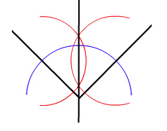
Bisecting an angle with straightedge and compass. Click here to see an animation of the construction.
One of the most famous mathematical problems of antiquity was to divide an angle into three equal parts using just a straightedge (a ruler without markings) and a compass. It's easy to divide an angle into two equal halves using those two tools (see the picture on the right or read this article). But is there a similar construction that guarantees to divide any angle into three? People tried to find one for over two millennia, until the French mathematician Pierre Wantzel showed in 1837 that you can't do it — there is no way you can trisect an angle drawn on a flat piece of paper using only a straightedge and a compass.
If I were a carpenter...
In this article we'll show that the problem becomes possible if you allow yourself to make use of the third dimension. The idea is inspired by woodwork and carpentry. For centuries journeymen carpenters rarely enjoyed the benefit of formal schooling, and many were illiterate. Yet geometry is at the heart of their profession. So they developed thousands of tricks and shortcuts to lay out a project without resorting to maths.
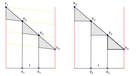
For example, how would you divide a $10 \frac{11}{16}$ wide board into three equal planks? Dividing the width by three, and then trying to locate $3 \frac{9}{16}$ and $7 \frac{1}{8}$ on a ruler is fraught with error. Instead, they laid a ruler on the board at an angle, making sure that the length measured by the ruler on the board was easily divisible by three. They then split the width as follows: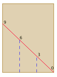
The brown rectangle represents the board. The red line represents the ruler, which has been placed so it measures a length easily divisible by 3 (9 in this case). The dashed blue lines then give the lines that divide the board into three equal planks.
In woodworking dimensions are often transferred from one surface to another by scribing. For example, to align a dove tail joint around a drawer corner, the front and sides are clamped together and the layout lines are scribed through — no measuring, no chance for numerical error. Similarly, before turning on a lathe, profile shapes are transferred from the lumber's edge to the faces of a nascent table leg.
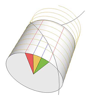
So I wondered if a similar trick could be used to divide an angle into three equal sections with just a compass and a straightedge using the third dimension. Often, moving to a higher dimension simplifies a problem. Can you draw a circle with only a straightedge? Not on a flat plane, but on the surface of a sphere, a straight line eventually returns to itself, forming a circle of longitude. No compass required!
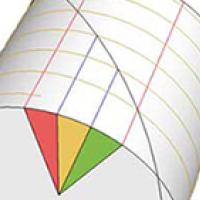
As it turns out, moving from the plane to the surface of a cylinder converts dividing an angle into three parts with a compass and straightedge into simply dividing a rectangle into three "boards". The straightedge alone suffices, and the intersection with carpentry tricks is a tight fit.
The construction
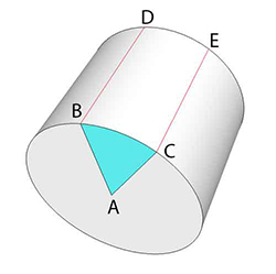
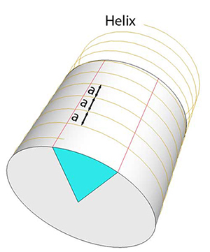
The original angle is trisected exactly, using only a (flexible) straightedge.
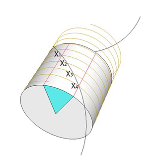
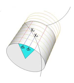
The proof
Why doesn't it work in the plane?
Is there a way of projecting this set-up onto two dimensions and come up with a straightedge and compass construction to trisect the angle in the plane? The answer, you won't be surprised to hear, is no. Our construction above only worked because the line segment $L$ was allowed to double up as an arc of a circle on the one hand and the edge of a flat rectangle on the other. This was only possible because we were allowed to roll a flat piece of paper up to form a cylinder — which requires the third dimension.However, while playing with this construction I came up with some approximate methods for trisecting an angle in the plane. You can find out more on my website.
About the author

Greg Blonder is a Professor of Manufacturing and Product design at Boston University, and formerly the Chief Technical Advisor at AT&T and a research VP at Bell Labs. His favourite book as a child was The World of Mathematics by J.R. Newman.
Comments
Anonymous
Thank you Professor Blonder. That problem has intrigued me since I took Geometry in high school.,
Jim Oss
Retired Science teacher
Wa Keeney, Kansas
Anonymous
Thank you very much sir for the lucid explanation. It is wonderful. I loved it.
Regards,
Awani Kumar
India